Woodworking shop layout templates let you experiment with equipment placement before moving heavy tools or installing permanent storage.
You do not need architectural software to make a useful plan. Graph paper, a ruler, and movable paper cutouts can help you compare arrangements. The important part is using consistent measurements and showing the space needed to work—not just the space occupied by equipment.
This guide explains how to create a reusable room drawing, make scale tool templates, and test layouts against real projects.
Affiliate disclosure: This article contains affiliate links. If you purchase through these links, we may earn a commission at no additional cost to you.
Planning your workshop from the beginning? Explore Ultimate Small Shop as an additional planning resource.
What a Useful Workshop Layout Template Includes
A workshop template has three main parts:
- A measured room outline showing walls, openings, and fixed obstacles.
- Movable equipment blocks representing benches, machines, and storage.
- Working-space outlines showing material movement, operator positions, and access needs.
Keep these parts separate so you can rearrange equipment without redrawing the room.
A neat drawing is helpful, but accuracy matters more than appearance. A simple rectangle drawn to the correct scale is more useful than a detailed machine picture with the wrong dimensions.
If you are still deciding which work zones you need, read our small woodworking shop layout guide first.
Step 1: Measure the Usable Interior
Measure inside the finished walls. Do not rely on a building’s advertised exterior dimensions.
Start with a rough sketch and write the actual measurements directly on it. Convert them into a scale drawing afterward.
Record the following:
| Feature | Measurements or details to record |
|---|---|
| Walls | Interior length of each section |
| Doors | Opening width, position, and swing |
| Windows | Width, position, and sill height |
| Columns and projections | Footprint and distance from reference walls |
| Ceiling obstacles | Location and height above the floor |
| Fixed equipment | Footprint and required access |
| Outlets and switches | Position and mounting height |
| Shared storage | Footprint, doors, and drawers |
Use a consistent reference point
Choose one corner as your starting point.
Measure the position of each feature from that corner or another clearly marked reference. For example, record the distance from the front-left corner to the near edge of a doorway.
This reduces confusion when transferring measurements onto paper.
Check the room’s shape
Do not assume an older room is perfectly rectangular.
Compare opposite walls and, where practical, measure both diagonals. Differences can indicate that your drawing needs to reflect an irregular shape. Recheck unexpected measurements before proceeding.
Record height separately
A floor plan cannot show every vertical conflict.
Add notes for low beams, garage-door tracks, window sills, and wall-mounted equipment. These can affect tall storage and the movement of long boards even when the floor appears clear.
Use our workshop planning checklist to keep these observations organized.
Step 2: Choose One Drawing Scale
Use the same scale for the room and every equipment template.
For a small workshop, ¼ inch on paper representing 1 foot in the room is a convenient starting point. On graph paper with ¼-inch squares, each square represents one square foot.
| Actual measurement | Drawing size at ¼ inch = 1 foot |
|---|---|
| 1 foot | ¼ inch |
| 2 feet | ½ inch |
| 3 feet | ¾ inch |
| 4 feet | 1 inch |
| 6 feet | 1½ inches |
| 12 feet | 3 inches |
| 20 feet | 5 inches |
For measurements recorded in inches, divide by 48 to find the drawing measurement in inches.
For example:
30-inch cabinet depth ÷ 48 = ⅝ inch on paper
Write the scale prominently on the drawing.
Use a larger scale when needed
If small equipment blocks become difficult to handle, use ½ inch = 1 foot.
At that scale, a 12×16-foot room becomes a 6×8-inch rectangle, before adding dimensions and notes. Choose paper large enough to leave room around the drawing.
If you work in metric units, 1:50 is another option: 1 meter becomes 2 centimeters on paper. Keep the units consistent throughout.
Step 3: Draw a Reusable Room Outline
Draw the walls and fixed features first.
Include door swings, permanent storage, and areas that must remain accessible. Label openings so you can distinguish an entry door from a garage opening or closet.
Keep one clean copy of this base drawing.
Use additional copies for layout experiments, or place tracing paper over the original. This prevents a promising arrangement from disappearing under layers of eraser marks.
For room-size examples, compare our 10×12, 12×16, and 12×20 workshop floor plans.
Step 4: Make Movable Equipment Templates
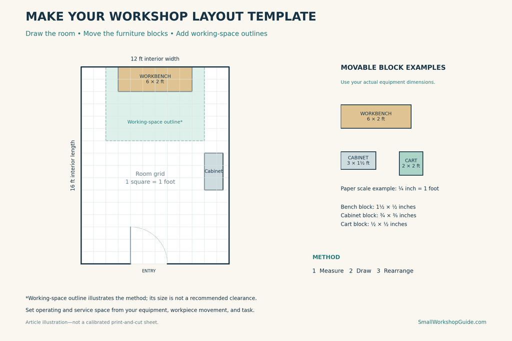
Measure the complete equipment setup before cutting out its template.
A machine’s tabletop dimensions may exclude fence rails, handles, motors, stands, and other projections. Include these in the footprint.
For irregular equipment, either draw its actual outline or use a rectangle that contains the entire footprint. The rectangle is simpler, but it may overstate the occupied space.
Example template sizes
The following dimensions are examples for practicing the method, not recommended sizes for every shop.
| Item | Example actual footprint | Paper template at ¼ inch = 1 foot |
|---|---|---|
| Workbench | 6 × 2 feet | 1½ × ½ inches |
| Assembly table | 4 × 3 feet | 1 × ¾ inches |
| Tool cart | 2 × 2 feet | ½ × ½ inches |
| Storage cabinet | 3 × 1½ feet | ¾ × ⅜ inches |
Label each cutout with the item’s name and actual dimensions.
Also mark the operator’s side or normal stock-feed direction where relevant. A rectangle without orientation can make an unsuitable arrangement look workable.
Distinguish measured and estimated dimensions
If you have not purchased a tool, label its block “provisional.”
Replace estimated dimensions with verified specifications before building storage or committing to its position. Do not use a generic tool symbol as proof that a particular model will fit.
Working through your equipment choices alongside the drawing? Take a look at Ultimate Small Shop as an additional workshop-planning resource.
Step 5: Add Working-Space Outlines
The equipment block shows where an item sits. A separate outline should show the space needed to use it.
Include:
- The operator’s working position.
- Material movement throughout the operation.
- Auxiliary supports.
- Access to controls and adjustments.
- Door, drawer, and service-panel movement.
- Relevant hose connections and projections.
Use the manual for the exact machine when establishing requirements. Grizzly’s site guidance, for example, considers the largest workpiece, auxiliary equipment, and maintenance access when allocating space.
Trace the material’s movement
Make a paper strip representing a typical long board.
Move it through the proposed operation on your drawing. Check the starting position, the movement through the tool, and the finishing position.
For equipment that rotates or swings, consider the full movement. A workpiece may clear an obstacle in one position and strike it in another.
This paper exercise helps identify conflicts. It does not replace the equipment manual or a physical check.
Keep access routes separate
Use a distinct line or shading for routes that must remain available.
A stock-handling area is not automatically a suitable walkway while the tool is operating. Consider how another person entering the room could affect the operation, even if you normally work alone.
Step 6: Draw Parked and Operating Arrangements
Mobile equipment needs more than one position on the plan.
Create separate versions for:
- Stored: Equipment parked and the room reset.
- Working: Tools positioned for a particular operation.
- Assembly: A project occupying the assembly surface.
This reveals problems that a single drawing can hide.
For example, a movable table may free space when empty but remain occupied by a clamped project for several hours. Your layout should still function in that condition.
If two tools share an operating area, check each arrangement separately. Confirm that the inactive tool can be moved somewhere practical without blocking an exit or another necessary area.
Step 7: Compare Layouts Using the Same Project
Create two or three arrangements, then test each against the same representative project.
A small cabinet or shelf can provide a useful sequence: bring in material, prepare parts, cut joints, assemble, and move the finished piece outside.
Use a comparison table:
| Question | Layout A | Layout B |
|---|---|---|
| Can material enter without rearranging equipment? | ||
| Is stock travel clear for each operation? | ||
| Can required drawers and cabinets open? | ||
| Is there somewhere to stage cut parts? | ||
| Can a project remain on the assembly table? | ||
| Are exits and service access preserved? |
Record specific problems instead of simply scoring a layout as “good.”
For example, “assembly table blocks cabinet drawer during glue-up” gives you something concrete to fix.
Our woodworking shop workflow guide explains how to assess the sequence from lumber storage to assembly.
Paper Templates or Digital Layout Tools?
Both can work.
| Method | Useful features | Limitation to watch |
|---|---|---|
| Graph paper and cutouts | Quick to rearrange; simple to learn | Small pieces can be difficult to handle |
| Spreadsheet drawing grid | Easy to duplicate and annotate | Cell proportions and printing scale need checking |
| General drawing software | Convenient layers and movable shapes | Objects may not retain real dimensions unless configured |
| CAD software | Precise dimensions and reusable blocks | Requires more setup and familiarity |
Choose a method that lets you enter or preserve actual dimensions.
When printing a digital plan, include a calibration line labeled with its intended printed length. Measure it with a ruler after printing. “Fit to page” settings can change the scale.
Do not mix cutouts printed at one scale with a room outline printed at another.
Step 8: Test the Drawing on the Floor
Mark the main footprints with painter’s tape before installing permanent fixtures.
Walk through the planned operations with tools switched off. Check access to storage, the movement of materials, and the route to the exit.
Use lightweight mockups where handling actual stock would be awkward.
If the room feels more crowded than the drawing suggested, identify what was missing: an accessory, your working position, a hose, or the space needed to turn a board.
Update the template and date the revised version.
Frequently Asked Questions
Can I use generic machine templates?
Yes, for early comparisons. Before committing to a layout, replace them with dimensions and operating requirements for your actual equipment.
Do I need a three-dimensional drawing?
Usually, a measured floor plan with height notes is enough to begin. A side view can help where low ceilings, wall storage, or overhead obstructions create conflicts.
Should every working-space outline stay separate?
Some areas may be shared when operations happen at different times. Check each operating arrangement individually and preserve required access.
How often should I update the plan?
Update it when equipment, storage, or typical project sizes change. Keep the previous version so you can see why you moved something.
Make the Template Match the Workshop
A useful workshop layout template is a working document.
Measure the room, draw everything at one scale, and distinguish equipment footprints from operating space. Compare arrangements using the same project, then check the preferred layout in the actual room.
Ready to develop your broader workshop plan? Explore Ultimate Small Shop here.