Planer and jointer placement depends on the boards you process as much as the machines themselves. A compact machine can still need substantial space when long material travels through it.
Start by mapping the complete board path, operator access, and extraction connections. Then decide whether each machine will remain in its operating position or move from storage when needed.
In a small workshop, a shared operating area can be practical. The important distinction is between where a tool fits when parked and where it can be used properly.
Affiliate disclosure: This article contains affiliate links. If you purchase through these links, we may earn a commission at no additional cost to you.
Planning equipment positions before setting up your shop? Explore Ultimate Small Shop as an additional planning resource.
Understand the Different Jobs and Movements
A jointer and thickness planer perform related but different tasks.
A jointer is commonly used to establish a flat face or straight edge. A thickness planer makes the opposite face parallel to an appropriate reference face while reducing the board to a consistent thickness.
Their operating arrangements differ.
| Planning consideration | Jointer | Thickness planer |
|---|---|---|
| Material movement | Operator guides stock across the tables | Feed rollers move stock through the machine |
| Operator access | Working space along the operating side | Access to the designated feeding and receiving positions |
| Main projections | Tables, fence, guard, and adjustment mechanisms | Extension tables, handles, controls, and dust connection |
| Layout concern | Long stock plus the operator’s working movement | Clear travel at both ends and access around the machine |
A normal planer pass does not automatically flatten a warped board. Your stock-preparation method affects both the equipment you need and the space it requires.
If you are still deciding whether to buy these machines, read our guide to whether a small shop needs a planer and jointer.
Start With the Exact Machine Manuals
Use the instructions for your actual models.
Record the complete dimensions and requirements for:
- Installation and mounting.
- Operating position.
- Permitted workpiece dimensions.
- Stock support.
- Guards and controls.
- Dust or chip extraction.
- Maintenance access.
- Compatible mobile bases or stands.
Minimum stock dimensions and operating procedures vary. Do not shorten material merely to make it fit the room without checking whether the resulting pieces are suitable for the machine.
Manufacturer site-planning guidance considers the largest workpiece, auxiliary equipment, and service access—not just the machine footprint.
Map the Entire Board Path
Choose the longest and widest material you regularly expect to process.
Draw its starting position, movement through the operation, and finishing position. Add any required supports and the operator’s working area.
For both machines, stock may extend well beyond the equipment at different stages.
Check more than the floor plan
A board may pass above a low cabinet, but that does not automatically make the arrangement suitable.
Check for handles, stored objects, hoses, adjacent workpieces, and other projections at the material’s actual height.
Also consider the movement needed to bring the board into position. A clear straight path through a machine is not enough if you cannot turn the material into that path.
Keep exits available
Do not depend on blocking the only exit with stock, supports, or a parked machine.
A doorway can look like useful additional space on a drawing while creating problems during operation. Assess access, conditions beyond the opening, and the full support arrangement before relying on it.
Give the Jointer Room Along Its Operating Side
A jointer needs space for the operator’s prescribed stance and movement as the board travels across its tables.
Position it so nearby furniture does not force an awkward approach or interrupt that movement.
Check:
- Access to the switch.
- Fence adjustment and tilt.
- Guard movement.
- Clearance for long material at both ends.
- Space for the workholding devices specified in the manual.
- Extraction connections.
- Maintenance access.
A wall position may work—but measure it
Placing the non-operating side near a wall can preserve central floor space.
However, the fence mechanism, dust connection, or service requirements may need additional room. Check the complete machine rather than assuming its table edge can sit against the wall.
Avoid squeezing the operating side into a narrow passage between the jointer and another tool.
Give the Planer Clear Feeding and Receiving Areas
A planer’s cabinet or benchtop footprint can be misleadingly small.
Draw its extension tables in their working positions and account for stock travel beyond them. Include access to height adjustments, controls, and any other components used during operation.
Follow the manual’s instructions for operator positioning. Do not treat the board’s feed line as a place for people to stand.
Allow a route around the machine
Where your operating procedure requires access to different sides, ensure you can move around the machine without stepping over supports or hoses.
Do not plan to reach across the cutting area or through the machine to compensate for restricted access.
Check the stand as well as the planer
A benchtop planer needs a suitable, securely mounted support arrangement.
Include the stand’s legs, casters, braces, and shelves in the drawing. A compact top does not necessarily mean a compact floor footprint.
Compare Fixed and Mobile Arrangements
| Arrangement | Potential benefit | Main limitation |
|---|---|---|
| Both machines fixed | Consistent setup and ready access | Requires permanent operating space |
| Fixed jointer, mobile planer | Retains a regular jointing position while sharing planer space | Planer setup must be repeated |
| Both machines mobile | Allows flexible use of a central area | More movement, connection changes, and setup checks |
| Combination machine | Combines functions within one machine | Requires room and time for mode changes |
Fixed positions
Fixed equipment can suit frequent milling, provided the room accommodates the complete operating areas.
The machines do not have to sit directly beside each other. A workable material route and clear access matter more than proximity alone.
A shared operating area
One machine can occupy a central area while the other remains parked.
Draw each operating arrangement separately. Confirm that the inactive machine is outside the active board path and does not block access.
Do not assume two operating areas can overlap simply because you intend to use only one machine at a time. The parked equipment must still be somewhere.
Combination jointer-planers
A combination machine can reduce duplicated equipment footprint, but it still needs operating space for both functions.
Check whether changing modes requires lifting tables, moving a fence, repositioning extraction, or accessing another side. Include the raised or repositioned components in the layout.
Comparing permanent positions with a shared milling area? Take a look at Ultimate Small Shop while developing your workshop plan.
Draw Parked and Operating Positions Separately
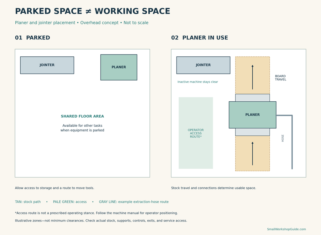
For movable equipment, create two versions of the layout.
Parked arrangement
Show:
- Stored equipment dimensions.
- Folded tables, where applicable.
- Hose and cord storage.
- Access to nearby cabinets.
- The route used to move the machine.
Operating arrangement
Show:
- Deployed tables and accessories.
- Complete stock travel.
- Required supports.
- Operator access.
- Extraction connections.
- Clear exits.
Use a compatible base or stand and follow its instructions for securing the equipment before use. A wheel lock alone should not be assumed to satisfy every machine’s stability requirements.
Do not move equipment while it is running.
Plan Chip Extraction Before Finalizing Positions
Planers and jointers can produce substantial amounts of chips during stock preparation.
Check the machine’s extraction requirements and the capabilities of the connected system. A hose that fits the port does not, by itself, establish that the system is suitable.
Route the hose outside the board path
Check the hose with tables deployed and the machine in its operating position.
It should not lie where stock will catch it, obstruct controls, or cross the operator’s route unnecessarily.
Support and route connections according to the equipment instructions, allowing access for inspection and cleaning.
Do not confuse chip ejection with collection
Some planers use fan-assisted chip ejection. That feature moves chips out of the machine; it does not by itself provide a complete collection arrangement.
Follow the manufacturer’s connection instructions.
Our dust collection hoses, ports, and separators guide explains the broader setup considerations.
Plan External Supports for the Actual Machine
Long material may need additional support as specified by the equipment instructions.
Do not transfer a support arrangement from one machine to another without checking its suitability. Jointer tables, planer beds, and external stands have different roles.
Position supports so they do not lift, twist, or obstruct the workpiece. Secure their adjustments and check the arrangement after moving equipment.
Our infeed and outfeed support guide covers stability, alignment, and storage.
Give Prepared Parts Somewhere to Go
Milling usually involves several passes and movements between stages.
Reserve suitable places for material waiting to be processed and for completed parts. Keep them outside operating areas.
Label reference faces and edges as appropriate to your project, and keep matching parts identifiable.
This helps prevent prepared material from accumulating on another machine’s table.
Plan the sequence around the actual project rather than an idealized straight production line. Our woodworking shop workflow guide explains how to coordinate preparation, joinery, and assembly.
Consider Buying Prepared Stock or Outsourcing Milling
If the required operating space does not fit, reconsider how you obtain prepared material.
Options include buying stock surfaced to suitable dimensions or having a supplier perform agreed milling operations.
Specify what you need: dimensions, reference surfaces, straight edges, and any allowances required for the project. Inspect the material when received; “surfaced” does not eliminate the need to check its condition and suitability.
Compare the full commitment of owning equipment with the frequency of use. Include storage, extraction, maintenance, and setup time.
For an occasional project, outside preparation may preserve valuable room for building and assembly.
Test the Arrangement Before Milling
With equipment disconnected and following the manuals, check the layout without performing a powered operation.
Use lightweight mockups where handling real boards would be awkward.
Confirm that:
- Stock can reach the starting position.
- Its complete travel is unobstructed.
- The machine and supports are secure.
- Controls and required adjustments remain accessible.
- Hoses and cords stay clear.
- The operator can use the prescribed working positions.
- Exits and necessary routes remain available.
- Completed parts have a designated destination.
Revise any arrangement that depends on reaching awkwardly, shifting equipment mid-operation, or balancing material without suitable support.
Frequently Asked Questions
Can a planer and jointer share the same operating space?
Yes, potentially, when used separately and the inactive machine is parked outside the active setup. Check each arrangement in full.
Can a jointer sit against a wall?
The non-operating side may be positioned near a wall if the manual, fence movement, connections, and maintenance access allow it.
Does a benchtop planer need much floor space?
Its stored footprint may be small, but long stock, supports, and operator access can require a much larger operating area.
Should the planer and jointer sit next to each other?
Convenience can help, but it is secondary to clear material paths and access. A short, manageable transfer between separated machines may work better.
Is a combination machine always the smallest solution?
It may reduce equipment footprint, but assess operating space, conversion requirements, and access for both functions.
Plan for Milling, Not Just Storage
A practical planer and jointer layout accounts for the board’s entire journey, the operator’s movements, and the extraction setup.
Compare fixed and mobile positions, test the complete operation, and leave somewhere for prepared parts. If the room cannot support the intended work, change the preparation method before forcing more equipment into it.
Ready to develop your broader workshop arrangement? Explore Ultimate Small Shop here.